2020-11-23
I plan to take some gliding lessons, and hope to accelerate my learning by spending some time on a simulator. But I know this will only be worthwhile if the controls on the sim are a reasonable approximation of the real thing - you don't fly an aircraft with a keyboard and mouse. So I need some half decent controls: a joystick and pedals. It's not too hard to get an old but ok joystick on ebay, but flight sim pedals are expensive and hard to obtain here in Australia. So I set out to construct some of my own. Like all homebrew projects, this was more effort than I expected. But I'm happy with the results, and the project let me work on my 3D design and printing skills, and also some embedded rust development.
The hardware
A internet search for DIY flight pedals returns plenty of images, but few documented designs. I copied the simple mechanical arrangement commonly used, and set out to replicate it with a combination of aluminium tubing and 3D printed parts. 3D printing is excellent for small detailed components, but lacks the strength required for larger components, and takes too long to print them in any case. Hence I find that an approach using off-the-shelf dimensioned metal or timber from the local harware store, in combination with 3D printing parts works really well.
The photos below show the physical construction:
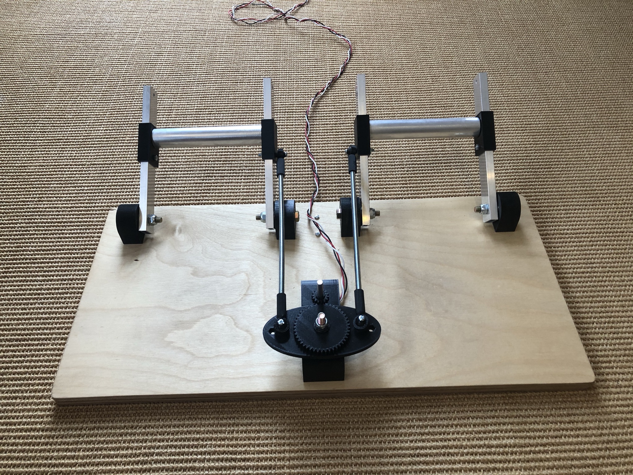

The 3D modelling was done with solvespace for some components, and openscad for others. I favour open source cad tools for the same reason I prefer open source software tools: I want to own my creative efforts indefinitely, and only open source tooling can ensure this.
The 3D designs are relatively straightforward. If you have access to a 3D printer it's well worth lurking in places like hackaday to discover tips and trick - I use a couple here.
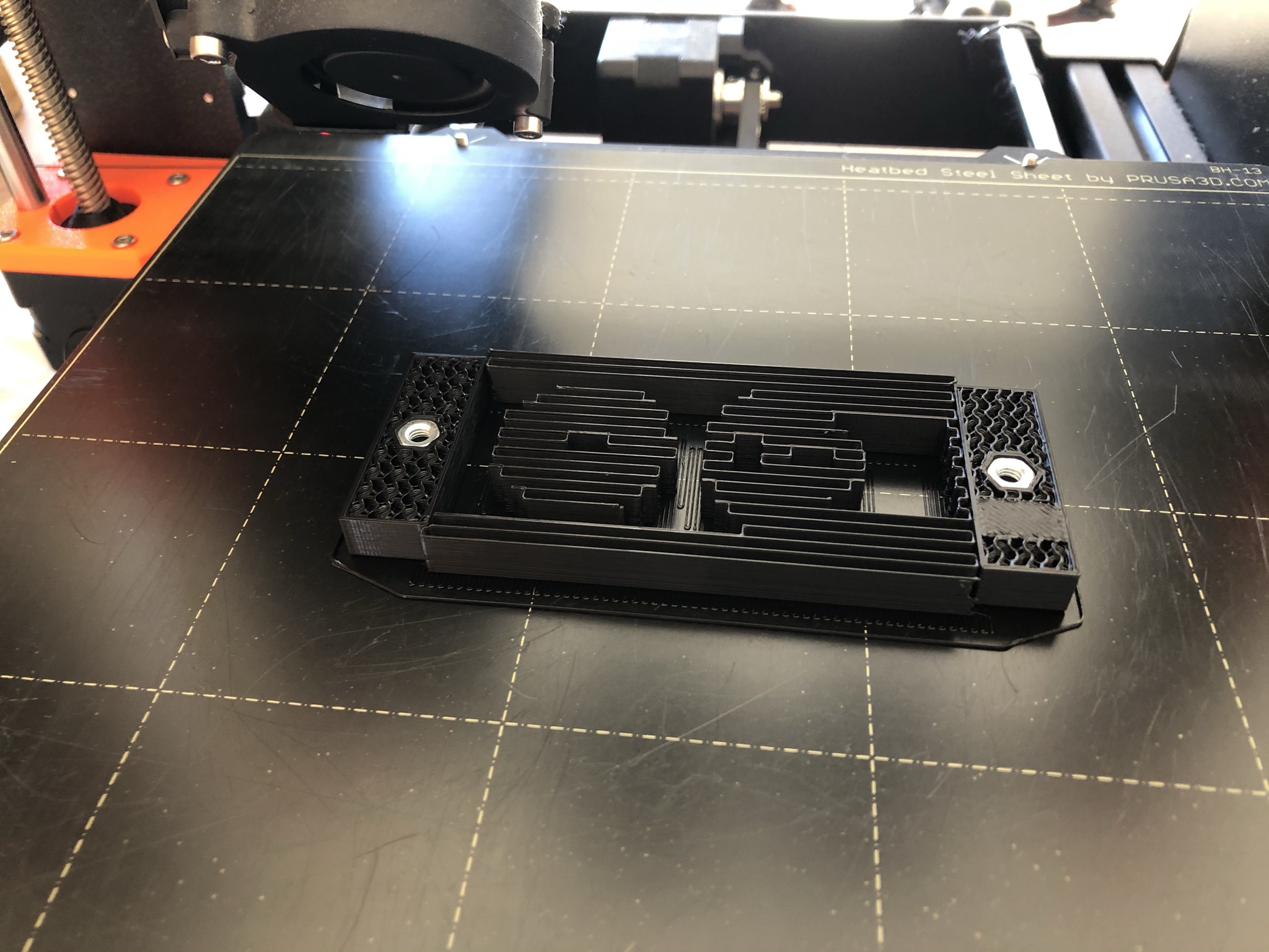
The mounts that attach to the baseboard embed M4 nuts inside them. The idea here is that you design the model with an internal void for the nut, and arrange for the 3D printer to pause for the nuts to be inserted, after which printing is resumed and the nut ends up completely encased. A photo of the paused print:
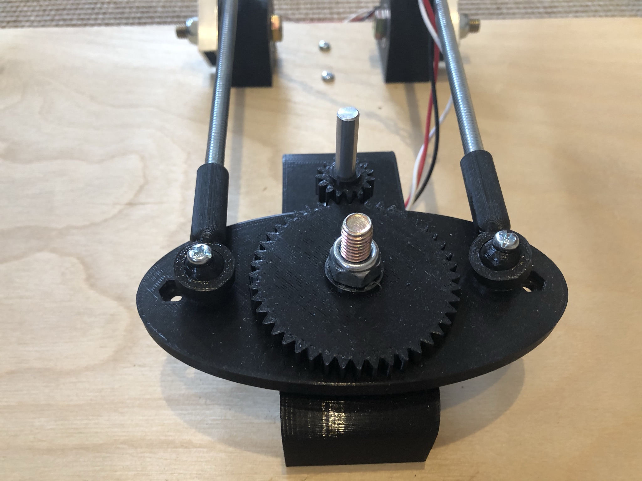
The ball joints connect the pedals to the lever arm via threaded rod. These are typically manufactured in metal, and are not inexpensive. The 3D printed design I used came straight from thingiverse. It's clever in that the ball is printed within the socket that wraps it, with a gap that is tuned to be as tight as one's printer can support. In practice the ball end up slightly fused to the socket, but one simply snaps it loose one printing is completed. I'm surprised how well these joints works - they are smooth enough in operation, and there is little slack. The non-smooth plastic on plastic connection will almost certainly wear out with enough use, but in that case it would be a quick job to reprint replacements. In summary - good enough for this purpose!
The electronics
The electronics is so simple it doesn't warrant a schematic diagram. It is an off-the-shelf blue pill development board, with a 10k linear potentiometer wired as a voltage divider on to input pin A0. Power is supplied via the USB port.
The software
The rust programming language intrigues me. I love the idea of a statically typed, modern programming language that can fit into the niches currently dominated by C/C++. High performance code is one such niche, but another is the ability to run "bare metal" on cheap microcontrollers.
Hence while a common approach to building a custom USB HID controller like this would be to use an arduino with a usb joystick library with code written in C++, I wanted to use rust, and chose the ubiquitous and cheap "blue pill" board. Getting an embedded development environment up and running can be a huge time suck - luckily this board is well supported in the embedded rust world, with the excellent blue-pill-quickstart github template project. The project includes enough information to get up and running, and provides links to more detailed documentation. But at the end of it you've only made it as far as the "hello world" of embedded systems: a blinking led.
The requirements are simple, we need:
- Code to configure and manage the USB port so that it acts as a (single axis) HID joystick.
- Code to measure the voltage from the potentiometer using the microcontrollers ADC (analog to digital converter), and supply it to the joystick interface
But doing this from first principles would be a mammoth task. The reference manual for the microcontroller is 1100 pages, with the ADC documentation on pages 215-254, and the USB port on pages 622-652. And even if you studied that, you'd still need to read and understand large chunks of the USB specification to use it. The lesson here is that, even if the embedded computer is tiny, it's still highly complex and configurable, and just as on larger computers, we will need to leverage the libraries and code of others if we want to get things working in a reasonable amount of time.
The good news is that the embedded rust community is vibrant and has released a large collection of tools and libraries. However, its a small community, and there's only limited examples and tutorials to act as guides. And this is one place where rust's programming power and expressiveness makes life harder for learners. In order to work with a wide range of microcontroller architectures, CPUs, and physical boards, the open source libraries are often quite abstract, and need to be composed in collections of abstract APIs and concrete implementations.
After research and trial and error I established that the following rust crates would be needed:
- usb-device - abstract API for USB interfaces
- embedded-hal - Hardware Abstraction Layer for ADCs (and many other types of hardware)
- stm32f1xx-hal- implementations of the above abstractions for the cpu on the blue pill
- usbd-hid - protocol for HID USB devices
with the overall project cargo dependencies being:
[dependencies]
stm32f1xx-hal = { version = "0.5.2", features = ["rt", "stm32-usbd", "stm32f103" ] }
cortex-m = "0.6"
cortex-m-rt = { version = "0.6.8", features = ["device"] }
panic-semihosting = "0.5.2"
embedded-hal = "0.2.4"
usb-device = "0.2.5"
usbd-serial = "0.1.0"
usbd-hid = "0.4.4"
My development strategy was somewhat simplistic - I started with the working blinking led demo, and mutated it by adding features one at at time, often cutting and pasting example code from elsewhere, and then incrementally changing it to what I needed. Whilst unsophisticated, this approach was quicker and easier than getting a deep understanding of each of the libraries I used. A blocker though was that I was unable to find an example of the usbd-hid library being used to implement a joystick. This meant that I had to gain sufficient understanding of the USB HID specification to write the descriptor for a joystick.
Ultimately the entire code is currently only 160 lines of rust. But it was quite an effort to get there!
More Details
This project is not a design that I expect others to duplicate - there's several changes I'd make if I were to produce a second device. But in the interest of homebrew collaboration the code and 3d models are published in the project's github repo.
Future plans
I was expecting to have to implement some calibration in the software, as the potentiometer only turns through a fraction of the total rotational range. And centering the pedals doesn't result in an exactly mid range value from the ADC. But it turns out that the standard PC joystick driver calibration deals with both these issues. I'd still like to sort this out in the embedded code, and not rely on the driver.
Also, I'd like to make an enclosure for the electronics with some additional desktop slider controls for glider trim, flaps, and airbrakes. But the setup works well enough to get some simulated flight time - and right now that's my priority.